PETTY
PAINTBALL FIELD AND PROSHOP
512-601-3235
Serving Central Texas for 9 YEARS!!!

|
PETTY
PAINTBALL FIELD AND PROSHOP Serving Central Texas for 9 YEARS!!!
|
|
Tourneys, Playdays and Big Games Nel-Spot 707 Resto |
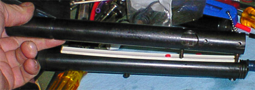
Let's put it back together! First, I had to build a few parts to make this happen.
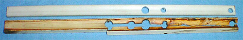
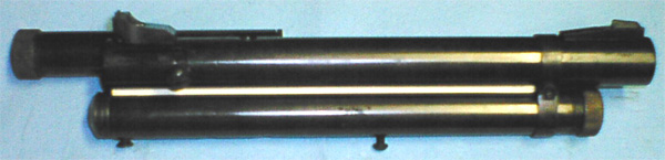
On top is a new barrel spacer that I just finished and am testing as a replacement for the 707. It has a few dozen shots so far and is looking very promising. The original is on the bottom and unfortunately is the norm for a 707. The new one is a "near exact" replacement for the 707 - the difference is in the barrel radius and 40 years of plastic evolution! The original plastic spacers supplied for the 707 were taken directly from the Crosman Pellet gun line. This is good and bad. The good is it's available from production guns of the period! Good luck finding a new one today. The bad is it was made for a pellet gun with a barrel diameter of approximately 1/2" and the 707 barrel approaches an inch! As the barrel is tightened down, the plastic splits down the center. On the new replacement I made, I used a radius that matched the barrel and maintained the proper spacing between the barrel and pressure tube.
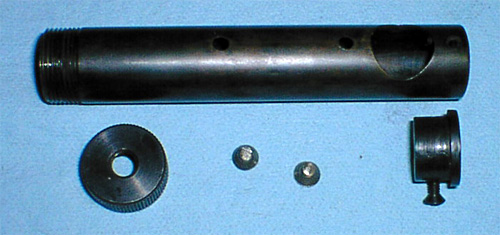
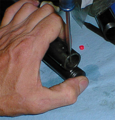
Here is a replacement feed tube that has been machined and ready to polish and re-blue. The replacement tube is a Crosman part from a broken 180 rifle. I also used the cap from the pressure tube by removing the internal plug and o-ring assembly. I had to spin a front plug from a piece of 1 1/8" mild steel. Having an old Bridgeport mill and an even-older SouthBend lathe on hand makes things a little easier.
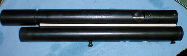
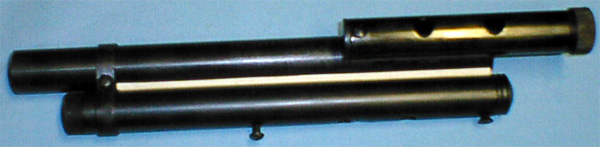
Here's the complete feed tube assembly ready for final finish.
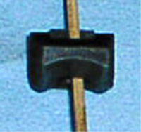
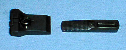
Here is a shot of the rear sight from a 150 that has had the radius cut to fit the 707. It's re-blued and ready to install.
Modified back sight and stock unmodified front sight and screw from 150 mounts directly to the 707. That's it for modified or hand built parts, let's get going... The parts are all back from machining and re-bluing and are ready to be assembled and shot...
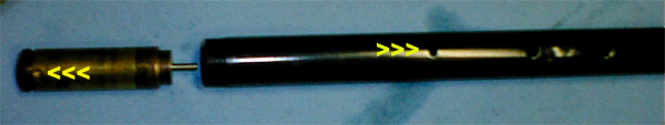
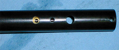
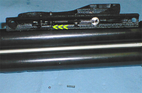
This is the valve assembly and pressure tube ready to start assembly. The yellow arrows point to the threaded hole in the valve and the hole where the valve hole will go. This is the bottom of the tube, you can tell by the indention pressed into the tube to stop the valve. Lube the o-ring on the valve and lightly oil the inside of the pressure tube, then line the two holes up and push the valve into the tube.
After the valve is slid into the tube, line up the threaded hole in the valve with the hole in the tube. You can use a 5/32" pin punch in the valve hole on the other side of the tube to help align the hole for the screw.
Take the front grip screw and install it into the hole a few turns after you line it up properly.
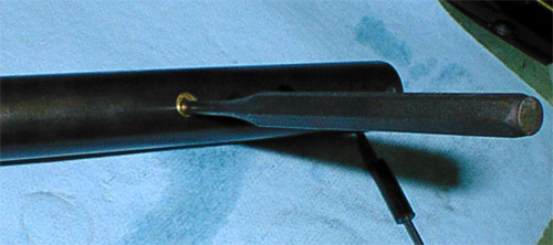
Turn the tube over after the screw is installed in the bottom and look at the hole in the top of the valve. Is it lined up with the center of the port or off center like this one. For maximum gas transfer and best seal, the port needs to be centered better.
Insert your handy 5/32 pin punch into the exhaust hole in the valve and turn the back half of the valve to center it in the hole for maximum gas transfer.
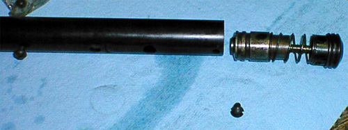
Get the hammer and cocking knob assembly and lube it up along with the inside of the back tube. Insert this into the back of the tube and install the screw that holds the back of the grip frame on the tube. You will have to push the cap into the tube as the spring will be pushing back. Line up the screw hole and install the screw finger tight to hold the assembly in the tube for the next step.
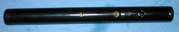
Here is the bottom tube with valve and hammer/cocking assembly in place with the bottom of the tube in the top of this picture.
Turn the pressure tube over and place the new white spacer and a macroline valve to barrel seal (the red piece, it can be any color, red just shows up good in pictures) in place. If you are lucky enough to have a good stock white Crosman spacer, the small radius goes up! The two screws are dropped down thru the holes in the back of the barrel and as this assembly is gently lowered onto the pressure tube assembly, start the two screws by passing a screwdriver thru the holes in top if the barrel assembly. The length of the macroline tube is a little long, but it's compressed when the screws and barrel band are tightened down and creates a good seal. I also drilled the white spacer for a 1/4" hole to hold and center the seal better.
I get the screws started, check for alignment, double-check alignment, then snug them up but don't tighten yet.
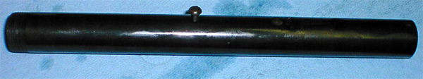
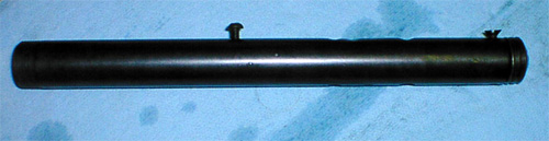
Here's the barrel and pressure tube together. I usually don't final tighten the screws until I have the barrel band on.
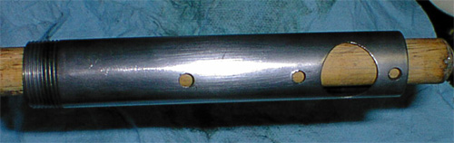
After installing and tightening the barrel band and also tightening the barrel to pressure tube screws installed in the previous step. I installed the feed tube with two screws, plug in front with screw and modified pressure cap for ball retainer. Most 707's will have the feed tube installed not only with the screws, but two tack welds on the underside also. The weld is stock from the factory as a result of feed tubes falling off as screws loosened during use!
After installing the modified rear sight, the stock 150 front sight and screw and the pressure tube cap. Need to re-blue the cap.....
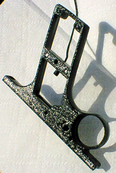
Here is a shot of the grip frame with the "correct wrinkle" paint for the era. After it's dry, clean out the holes and install all the parts.
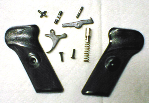
Here are the internals and grips from the grip frame - minus the spring and ball bearing from the safety. The parts have been reblued and polished as needed for smooth operation. These trigger assemblies can be made very smooth for match style pellet pistol shooting.
Here is a shot of the grip frame with the internals installed and ready for installation. The yellow arrows are pointing to the small hole where the ball bearing and spring at the bottom of the picture goes. When you are taking the gun apart, be very careful as you will loose this little rascal and it's darned hard to find! Remove the two screws from the bottom of the marker and get the frame ready to install. Lube the pivots and sear area with oil, then drop the ball bearing in the hole first, then put the spring on top of it. When the grip frame is installed on the bottom of the marker, the spring will be captured in the hole by the body.
Here is a picture of the marker with the frame installed.
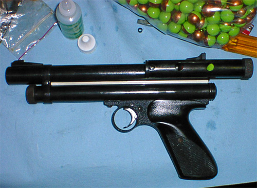
After you install the grips, she looks like this. The grips were washed with a toothbrush and rebuffed, then waxed - note no Crosman logo on the grips. Look closely, there is already some premium in the feed tube.......and a 12 gram in the chamber........Let's to outside. Pull the cocking device back all the way and pull the trigger to pierce the 12 gram, then shoot again just to make sure........chamber a ball, pull the cocking device back and shoot over the chrono......296, 290, 299, 292....ALRIGHTY THEN!!!! I never got this lucky with the other 707s they all shot in the 265 - 270 average range on high power and 165ish on low power.
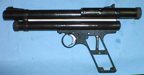
So, this is what it looks like?
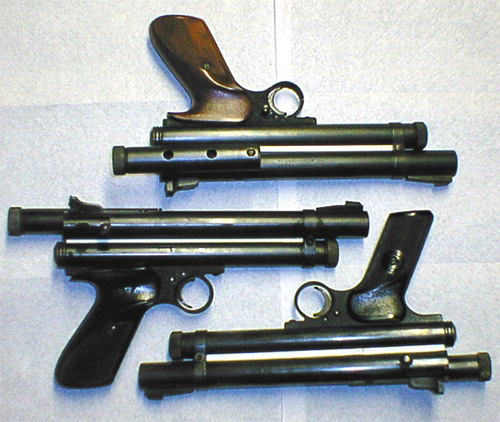
This is the rest of the family. As you can see, they came with various grips or were changed over the years.
|
Send mail to info (at) pettypb (dot) com with
questions or comments about this web site.
|